..........Generator
allows to generate square wave signal with frequency varying from 0,01
Hz to 60 kHz. Pulse ratio adjustments go from 3 to 97 %.

..........This generator can be used differently for adjustments of units and electronics circuits, to control circuits of switched power supplies, to estimate settings of low-frequency amplifier when square wave signal is passing, it is used for digital circuits. It can also adjust electronic musical instruments, exactly setting the frequency of music notes. The accuracy of frequency is up to 4 digits.
..........This generator can be used differently for adjustments of units and electronics circuits, to control circuits of switched power supplies, to estimate settings of low-frequency amplifier when square wave signal is passing, it is used for digital circuits. It can also adjust electronic musical instruments, exactly setting the frequency of music notes. The accuracy of frequency is up to 4 digits.
Circuit of adjustable pulse generator
..........Generator circuit is shown at the picture below:

..........Generator is assembled on microcontroller PIC16F628A. The circuit is simple and its components are easily available. Frequency and pulse ratio are controlled with 4 operation keys. 4-digit dynamic indication with short-time mode prompting messages.
..........Short-time prompting messages help to deal with modes while we operate the generator.
Generator operation
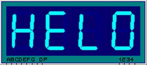
..........When we switch on the generator, display shows the greeting:
..........Then it prompts, that the frequency is being displayed:
..........Prompt of frequency digit (Kilohertz):

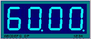
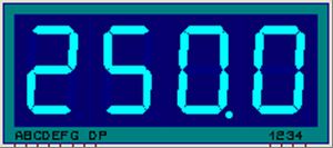
..........And frequency readings themselves. When frequency is displayed in kilohertz, the dot in the least significant digit of indicator is on:
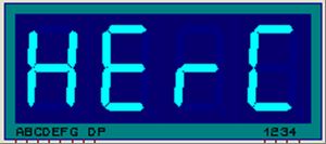
..........If in the process of adjustment the frequency is changed and there is a shift from kilohertz to hertz, then the display shows that digit change:
..........When frequency is displayed in Hertz, the dot in the least significant digit is off:
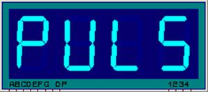
..........When pulse ratio is displayed, there is a prompt:
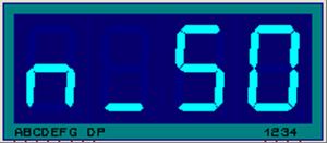
..........Ratio is displayed like this:
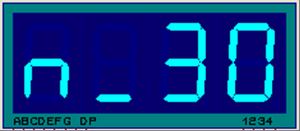
..........During the correction digits are corrected in pair, both frequency and pulse ratio:
..........In standard mode whether frequency or ratio is displayed, in this case digits do not twinkle, correction is switched off.
..........If frequency is displayed, and we need to get ratio then we should press one of the keys “pulse ratio+” or “pulse ratio-”. There will be a shift to ratio settings with half a second prompt “PULS”.
..........If ratio is displayed we can shift to frequency pressing the frequency correction keys Fosc+ or Fosc-.
..........Then it prompts, that the frequency is being displayed:
..........Prompt of frequency digit (Kilohertz):
..........And frequency readings themselves. When frequency is displayed in kilohertz, the dot in the least significant digit of indicator is on:
..........If in the process of adjustment the frequency is changed and there is a shift from kilohertz to hertz, then the display shows that digit change:
..........When frequency is displayed in Hertz, the dot in the least significant digit is off:
..........When pulse ratio is displayed, there is a prompt:
..........Ratio is displayed like this:
..........During the correction digits are corrected in pair, both frequency and pulse ratio:
..........In standard mode whether frequency or ratio is displayed, in this case digits do not twinkle, correction is switched off.
..........If frequency is displayed, and we need to get ratio then we should press one of the keys “pulse ratio+” or “pulse ratio-”. There will be a shift to ratio settings with half a second prompt “PULS”.
..........If ratio is displayed we can shift to frequency pressing the frequency correction keys Fosc+ or Fosc-.
Adjustment of output signal frequency
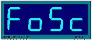
..........One of the keys Fosc+/ Fosc- is pressed in order to shift to frequency correction in the mode of frequency display.
..........At the same time “FoSc”, “HErC” or “H_Hc” prompts (depending on fixed digit number) are displayed successively. Then frequency value is displayed, meanwhile two corrected digits twinkle with 2 Hz frequency.
Fosc+ Fosc- keys correct twinkling digits. Holding down the key more than 1 second we get the autorepeat with frequency 20 times per second during correction.
..........To change the digit press the keys pulse ratio+ pulse ratio-.
..........Holding down the keys pulse ratio+ pulse ratio- more than 1 second in the frequency correction mode we get the shift to the mode of ratio display.
Adjustment of pulse ratio
..........The
keys “pulse ratio+” “pulse ratio-” are
pressed in the mode of ratio display to correct pulse rate. After
“PULS” prompt two digits of ratio twinkle with 2 Hz
frequency – in this mode is possible the correction of pulse
ratio.
..........Pressing the keys “Fosc+” “Fosc-” in the mode of ratio correction we shift to the display of current frequency.
..........If neither key is not pressed more than 10 seconds in the correction mode – then happens automatic shift to display mode of corrected settings – twinkle is switched off.
..........If zero frequency is set (at the indicator only zeros) the generator is switched off, low logic level is set at the output RB3.
..........Change of operation frequency at the output of device during correction happens after button up. Output signal is nulled at the moment of recount and frequency change (about one millisecond).
..........Microcontroller firmware ( HEX - file ) for this circuit can be bought from the author on condition that you are committed not to spread it in the internet or not to pass it to someone else. The firmware costs $9. Payment can be made through WebMoney.
..........Pressing the keys “Fosc+” “Fosc-” in the mode of ratio correction we shift to the display of current frequency.
..........If neither key is not pressed more than 10 seconds in the correction mode – then happens automatic shift to display mode of corrected settings – twinkle is switched off.
..........If zero frequency is set (at the indicator only zeros) the generator is switched off, low logic level is set at the output RB3.
..........Change of operation frequency at the output of device during correction happens after button up. Output signal is nulled at the moment of recount and frequency change (about one millisecond).
============================
..........Microcontroller firmware ( HEX - file ) for this circuit can be bought from the author on condition that you are committed not to spread it in the internet or not to pass it to someone else. The firmware costs $9. Payment can be made through WebMoney.
Inventor of the device
Vitaly Antonov
Chelyabinsk
Email is indicated on the circuit